Het principe
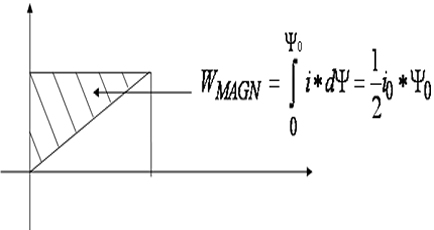
De brandstof van de Magneetconverter is de magnetische flux. Deze brandstof wordt geproduceerd door een a-symmetrisch magnetisch veld. De magnetische flux produceert een extra as-draaimoment.
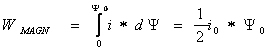
WMAGN= arbeid door het magnetisch veld
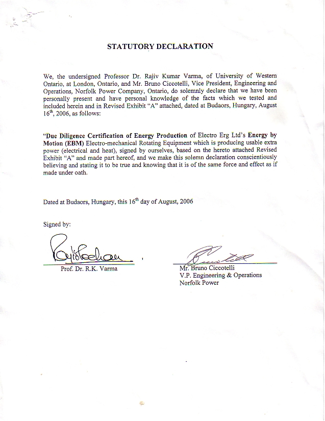
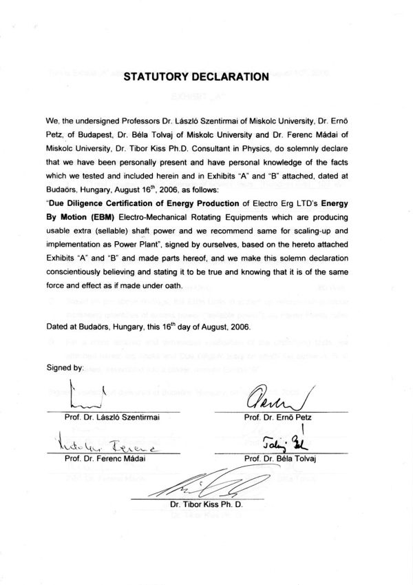
Hieronder vindt u enkele onafhankelijke verklaringen van diverse professoren uit zowel Europa als buiten Europa. Deze verklaringen luiden unaniem hetzelfde. De uitvinder en ontwikkelaar van deze technologie heeft hiervoor wereldwijd erkenning gekregen. In totaal zijn er 9 wereldwijde patenten gevestigd. Onderstaand zijn diverse opgaven afgebeeld.
---- Energie-opwekking door Magneettechnologie is een bewezen concept ----

voor vergroting : klik op het document
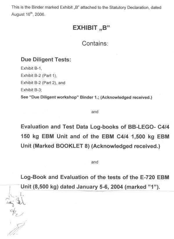
Statutory Declaration of European Professors
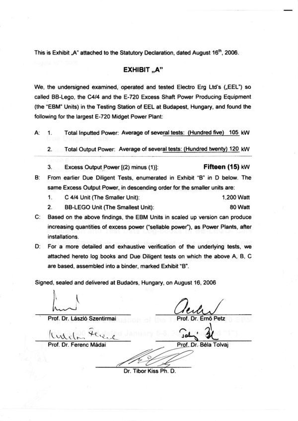
belangrijke opmerking: "open coil test" = uitsluitend gebruik van permanente magneten
----------------------------------------------------------------------------------------------------------
De uitvinder c.q de ontwikkelaar van dit alles is Dhr. Leslie Szabo. Op deze site worden in totaal 9 patenten genoemd, waarvan er 7 worden weergegeven.
1 ASYMMETRICAL ELECTRO-MECHANICAL DEVICE
Inventor: SZABO LESLIE I (HU) Applicant: ELECTRO ERG LTD (HU)
EC: IPC: H02K1/12; H02K1/12; (IPC1-7): H02K1/12
Publication info: CA2131961
1996-03-14
2 ASYMMETRICAL ELECTRO-MECHANICAL DEVICE
Inventor: SZABO LESLIE I (HU) Applicant: ELECTRO ERG LTD (HU)
EC: H02K19/18; H02K19/20 IPC: H02K57/00; H02K19/18; H02K19/20 (+3)
Publication info: NO943284
1994-09-06
3 ASYMMETRICAL ELECTRO-MECHANICAL DEVICE
Inventor: SZABO LESLIE I Applicant: ELECTRO ERG LTD
EC: IPC: H02K19/18; H02K19/20; H02K19/16 (+2)
Publication info: AU3743193
1993-10-05
4 METHOD OF INCREASING THE EFFICIENCY OF AN ELECTRICAL GENERATOR
Inventor: SZABO LESLIE I (HU) Applicant: ELECTRO ERG LTD (HU)
EC: H02K19/20; H02K19/24; (+1) IPC: H02K19/20; H02K19/24; H02K35/06 (+6)
Publication info: WO9213383
1992-08-06
5 COMMUTATORLESS DIRECT CURRENT MACHINE (CDC) in my patents list
Inventor: SZABO LESLIE I (HU) Applicant: ELECTRO ERG LTD (BS)
EC: IPC: H02K29/00; H02K29/00; (IPC1-7): H02K29/00
Publication info: CA2048719
1993-02-09
6 ROTOR/STATOR COMBINATION
Inventor: SZABO LESLIE I (HU) Applicant: ELECTRO ERG LTD (BS)
EC: IPC: H01R39/64; H02K16/00; H02K23/02 (+6)
Publication info: CA2036195
1992-08-13
7 METHOD OF INCREASING THE EFFICIENCY OF AN ELECTRICAL GENERATOR
Inventor: SZABO LESLIE I (HU) Applicant: ELECTRO ERG LTD (HU)
EC: IPC: H02K3/42; H02P9/14; H02K3/00 (+3)
Publication info: CA2033013
1992-06-22
8 COMPENSATION SYSTEM OF THE ALTERNATING CURRENT ELECTRIC
GENERATOR
Inventor: SZABO LESLIE J (HU) Applicant: ELECTRO ERG LTD (BS)
EC: IPC: H02K1/10; H02K3/28; H02K17/28 (+19)
Publication info: PL278317
1989-11-13
9 Compensation circuit for electrical generators.
Inventor: SZABO LESLIE I (CA) Applicant: ELECTRO ERG LTD (BS)
EC: H02P9/40 IPC: H02P9/40; H02P9/00; (IPC1-7): H02K3/00
Publication info: DD294138
1991-09-19
CA2131961
ASYMMETRICAL ELECTRO-MECHANICAL DEVICE
SZABO, Leslie I.
Applicant: ELECTRO ERG LTD (HU)
EC: IPC: H02K1/12; H02K1/12; (IPC1-7): H02K1/12
3-14-1996
Also issued as: NO943284 // AU3743193
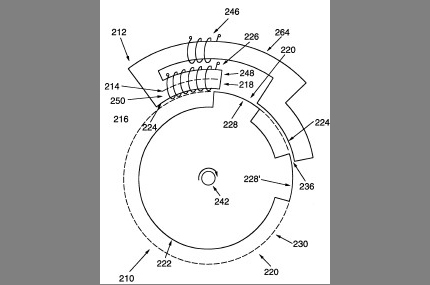
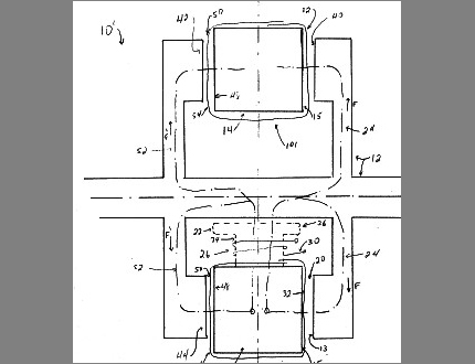
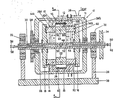
Abstract --- This invention relates to an asymmetrical, electro-mechanical device comprising a geometricallymagnetically-asymmetrical stator and a rotor which move with respect to each other. There is a stator air gap which makes the stator asymmetrical. The continuous magnetic flux path is still substantially planar. The magnetic flux passing from the rotor to the stator is interrupted when the rotor passes by the stator air gap. The stator has two faces with armature conductors on both faces and the rotor has two faces which successively interact with the two stator faces. In a further embodiment, the electromechanical device comprises a plurality of stators and rotor faces, each being substantially interchangeable. The invention is able to achieve improvements over the prior art electro-mechanical devices, particularly in respect of efficiency.
________________________________________
WO9213383
METHOD OF INCREASING THE EFFICIENCY OF AN ELECTRICAL GENERATOR
SZABO, Leslie I.
EC: H02K19/20; H02K19/24; (+1) IPC: H02K19/20; H02K19/24; H02K35/06 (+6)
8-06-1992
Abstract --- This is a method of increasing the efficiency of an electrical generator (10) of the type that generates real output power by a change of the reluctance of the magnetic flux path. The efficiency is improved by providing specific components, features and characteristics of the generator (10) in combination in accordance with a specific relationship so as to reduce the relative effect of the load. Also, the efficiency is improved by recognizing and reducing the effect of an alternating current superimposed on the excitation current.
________________________________________
CA2048719 ( Drawings)
COMMUTATORLESS DIRECT CURRENT MACHINE (CDC)
SZABO, Leslie I.
EC: IPC: H02K29/00; H02K29/00; (IPC1-7): H02K29/00
2-09-1993
Abstract --- The present invention relates to an electro-magnetic machine comprising a rotor and a stator moving relative to each other, a gap between the rotor and stator and an armature conductor positioned in the gap and associated with either the rotor or the stator. A magnetic flux generated by a magnetic flux generating means passes uni-directionally through the gap either into or out of the stator at a pole, through the stator, through a member magnetically connecting the stator and the rotor, into and through the rotor and out of or into the rotor at a pole and back to the gap. In this way, when the rotor moves relative to the stator, an electrical current or potential will be developed in the conductor and the machine will act as a generator. Alternatively, if current is made to flow in the armature conductor, the rotor will move relative to the stator and the machine will operate as a motor. ________________________________________
CA2036195 ( Drawings )
ROTOR/STATOR COMBINATION
SZABO, Leslie I.
EC: IPC: H01R39/64; H02K16/00; H02K23/02 (+6)
8-13-1992
Abstract --- Improvements to electro-magnetic-mechnical machines are disclosed. The improvements relate to improved geometrical structure for rotor/stator combinations; improved efficiency of operation; and d.c. motor/generators that do not require commutation. The improved geometrical structure eliminates the reversal of magnetic flux directions around the face of a rotor. This allows d.c. current to be supplied to, or derived from, the machine without the necessity of commutation. Also, improved efficiency is obtained by supplying the machine with reactive current and also using a filter to remove d.c. components from developed counter-potentials.
________________________________________
CA2033013 ( Drawings )
METHOD OF INCREASING THE EFFICIENCY OF AN ELECTRICAL GENERATOR
SZABO, Leslie I.
EC: IPC: H02K3/42; H02P9/14; H02K3/00 (+3)
6-22-1992
Abstract --- This invention relates to a method of increasing the efficiency of an electrical generator of the type that generates real output power by a change of the reluctance of the magnetic flux path. The efficiency is improved by providing specific components, features and characteristics of the generator in combination in acccordance with a specific relationship so as to reduce the relative effect of the load. Also, the efficiency is improved by recognizing and reducing the effect of an alternating current superimposed on the excitation current.
________________________________________
BR8901236A
COMPENSATION SYSTEM OF THE ALTERNATING CURRENT ELECTRIC GENERATOR
SZABO, Leslie I.
EC: IPC: H02K1/10; H02K3/28; H02K17/28 (+19)
11-13-1989
Also issued as: JP3164051 // PL278317
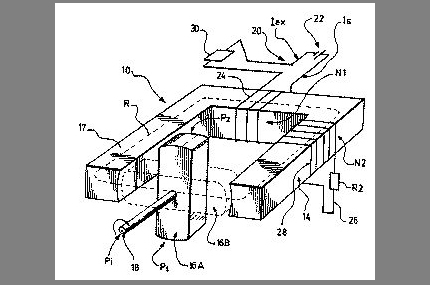
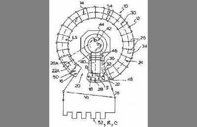
Abstract --- PURPOSE: To improve the efficiency in a generator by eliminating a magnetic flux distortion by a correction conductor or a coil that surrounds or is wound around one portion of a magnetic flux path. CONSTITUTION: A correction coil 30 is provided so that it is wound around or surrounds one portion of a magnetic flux path 12. Also, the correction coil 30 is connected to a power supply 32, and a correction voltage Vc is generated across the correction coil 30, where a correction magnetic flux Fc is induced when the correction current Ic flows into the correction coil 30, and the correction magnetic flux Fc has a constituent that opposes a secondary magnetic flux Fs being induced by a current Ia in an armature coil 22. Also, a correction current Ic has a non-constituent for the correction voltage Vc, thus reducing power input conditions for rotating a rotor 14 as a result of the correction magnetic flux Fc generated by the correction coil 30.
________________________________________
WO9318570
ASYMMETRICAL ELECTRO-MECHANICAL DEVICE
SZABO, Leslie
1993-09-16 Classification: - international: H02K57/00; H02K19/18; H02K19/20; H02K57/00; H02K19/16; (IPC1-7): H02K19/18; H02K19/20;- european: H02K19/18; H02K19/20 Also published as: EP0629317 // FI944074 // EP0629317 // BR9306036 // EP0629317
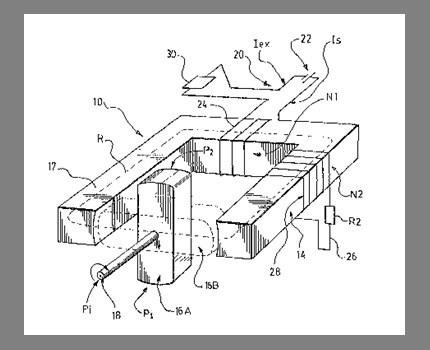
Abstract --- An asymmetrical, electro-mechanical device (10) comprises a geometrically-magnetically-asymmetrical stator (12) and a rotor (22) which move with respect to each other. There is a stator air gap (20) which makes the stator (12) asymmetrical. The magnetic flux passing from the rotor (22) to the stator (12) is interrupted when the rotor (22) passes by the stator air gap (20). The invention is able to achieve improvements over the prior art electro-mechanical devices, particularly in respect of efficiency.
________________________________________
DD294138
COMPENSATION CIRCUIT FOR ELECTRICAL GENERATORS
SZABO, Leslie I.
EC: H02P9/40 IPC: H02P9/40; H02P9/00; (IPC1-7): H02K3/00
9-19-1991